Turning a motorized mount smart with a Raspberry Pi Pico and CC1101 module
I recently bought a motorized mount for my TV to sit above the fireplace (yeah, I know, r/TVTooHigh…) . It came with a simple remote for UP, DOWN, and STOP commands, but since I rely on Google Home for most of my home automation, I wanted to integrate this mount into my smart setup.
My first step was to crack open the remote’s battery casing and check the FCC-ID, which revealed it transmits on 433.92 MHz. Grabbing my Flipper Zero, I captured and decoded the signal with no issues. It turned out to use the Dooya protocol, commonly found in blind shutters and other home appliances.
Filetype: Flipper SubGhz Key File
Version: 1
Frequency: 433920000
Preset: FuriHalSubGhzPresetOok650Async
Protocol: Dooya
Bit: 40
Key: 00 00 00 53 82 00 01 33
For the hardware, I chose a Raspberry Pi Pico 2W microcontroller paired with a CC1101 433 MHz module. I also 3D-printed a cool case to house everything neatly.
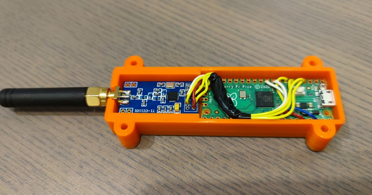
Wiring
I used the following wiring in my setup.
| CC1101 | Raspberry Pi Pico |
| ------ | ----------------- |
| GND    | GND               |
| VCC    | 3v3 OUT           |
| GDO0   | GP20              |
| CSN    | GP17              |
| SCK    | GP18              |
| MOSI   | GP19              |
| MISO   | GP16              |
| GPO2   | Unused            |
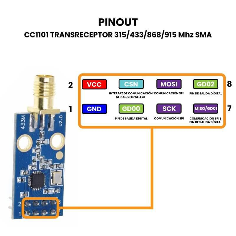
Wiring it up was straightforward, though I should note that other CC1101 might have a different pinout than mine since there are multiple versions of the circuit.
Signal Capture and Replay
The real challenge began with signal replay. I spent hours tinkering with CircuitPython and MicroPython, trying to mimic the ASK/OOK signals from the Dooya remote, but nothing worked. I drew from resources in this repo, which helped with transmitting strings and confirm that the module was working fine, but replaying the exact remote signal eluded me.
I stumbled upon this article, where they used an ESP32 with ESPHome to capture and replay Dooya signals. However, I did not want to install Home Assistant on my setup. Still, it introduced me to RadioLib, a versatile library for ESP32 and Arduino boards.
To my surprise, RadioLib also works with Raspberry Pi Picos! This discussion on the RadioLib repo was very useful for getting started. With some code snippets, I could transmit signals and verify them on my Flipper.
Building on that, I created a function to capture raw signals over 5 seconds. I’d press a button on the remote, and the code would print an array of edges via serial for copying and transmitting.
void captureRaw(uint32_t captureMs) {
int16_t st = radio.receiveDirectAsync();
if(st != RADIOLIB_ERR_NONE) {
Serial.print(F("receiveDirectAsync() failed, code "));
Serial.println(st);
return;
}
capCount = 0;
lastEdgeUs = micros();
lastLevelHigh = digitalRead(GDO0_PIN);
capturing = true;
attachInterrupt(digitalPinToInterrupt(GDO0_PIN), onGdo0Change, CHANGE);
uint32_t t0 = millis();
while(capturing && (millis() - t0 < captureMs)) {
yield();
}
capturing = false;
detachInterrupt(digitalPinToInterrupt(GDO0_PIN));
radio.standby();
// Append a tail duration for the last level (nice for replays)
uint32_t now = micros();
uint32_t dt = now - lastEdgeUs;
if(capCount < MAX_EDGES) {
capTimings[capCount++] = lastLevelHigh ? (int32_t)dt : -(int32_t)dt;
}
}
Pasting that array into a variable, I could then transmit it using a dedicated function.
void printCapturedAsArray() {
noInterrupts();
uint16_t n = capCount;
interrupts();
Serial.println();
Serial.print(F("Captured edges: "));
Serial.println(n);
Serial.println(F("const int32_t RAW[] = {"));
for(uint16_t i = 0; i < n; i++) {
int32_t v;
noInterrupts();
v = capTimings[i];
interrupts();
Serial.print(F(" "));
Serial.print(v);
if(i + 1 < n) Serial.print(',');
if((i % 8) == 7) Serial.println();
}
Serial.println();
Serial.println(F("};"));
Serial.println(F("const size_t RAW_LEN = sizeof(RAW)/sizeof(RAW[0]);"));
Serial.println();
}
const int32_t RAW[] = {

687434, -1513, 347, -751, 708, -359, 342, -771,

696, .........

};

const size_t RAW_LEN = sizeof(RAW)/sizeof(RAW[0]);
void transmitRawTimings(const int32_t* raw, size_t rawLen, uint8_t repeats, uint32_t gapUs) {
if(raw == nullptr || rawLen == 0) {
Serial.println(F("transmitRawTimings: empty RAW"));
return;
}
for(uint8_t r = 0; r < repeats; r++) {
int16_t st = radio.transmitDirectAsync();
if(st != RADIOLIB_ERR_NONE) {
Serial.print(F("transmitDirectAsync() failed, code "));
Serial.println(st);
return;
}
// Drive the line connected to CC1101 GDO0
pinMode(GDO0_PIN, OUTPUT);
for(size_t i = 0; i < rawLen; i++) {
int32_t v = raw[i];
bool level = (v > 0);
uint32_t us = (v > 0) ? (uint32_t)v : (uint32_t)(-v);
digitalWrite(GDO0_PIN, level ? HIGH : LOW);
// Split long delays into safe chunks
while(us > 0) {
uint32_t chunk = (us > 16000) ? 16000 : us;
delayMicroseconds(chunk);
us -= chunk;
yield();
}
}
// Idle low (common for OOK)
digitalWrite(GDO0_PIN, LOW);
radio.standby();
pinMode(GDO0_PIN, INPUT);
// Inter-frame gap
uint32_t g = gapUs;
while(g > 0) {
uint32_t chunk = (g > 16000) ? 16000 : g;
delayMicroseconds(chunk);
g -= chunk;
yield();
}
}
}
Using these functions, I was able to get my mount to move up and down programmatically. Nice!
Now, to tie it into my home automation, I needed to connect the Pico to Wi-Fi and link it to Google Home. I turned to two free services: IFTTT and Adafruit IO.
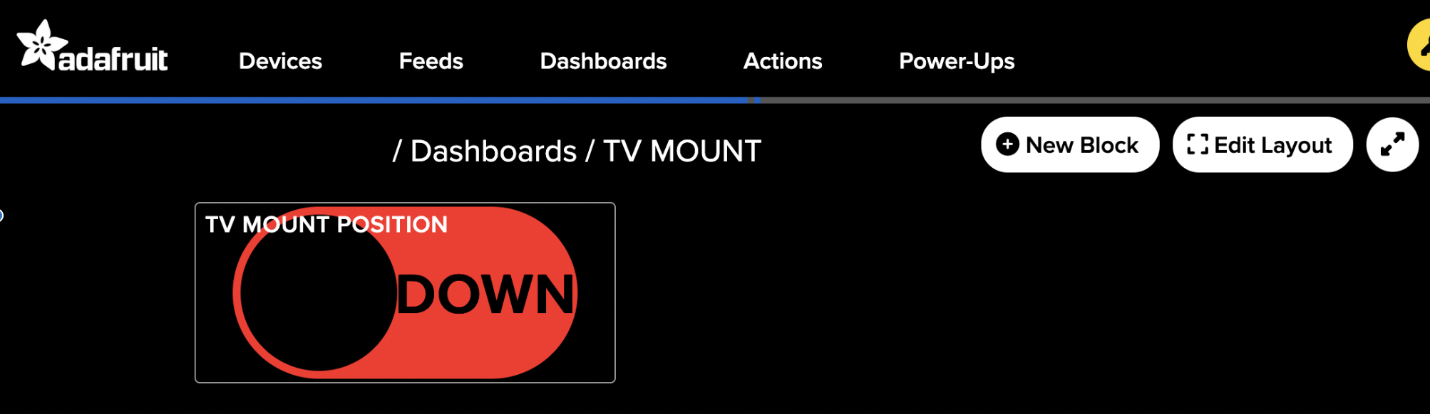
Setting up Adafruit IO was simple—after a free account, I created a feed and dashboard with a toggle switch for UP/DOWN commands.
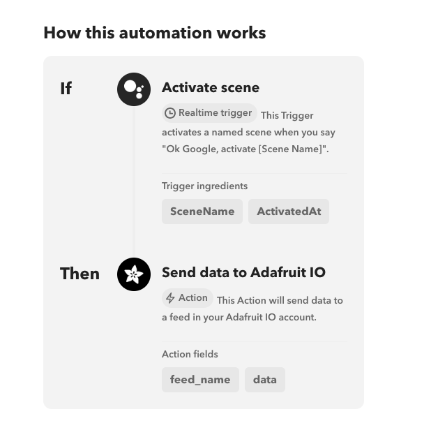
For IFTTT, I linked my Google Assistant and Adafruit accounts, then crafted an applet: when I say “Activate Scene” to Google, it sends data to my Adafruit feed.
Connecting the Pico
With everything configured, I connected the Pico to Wi-Fi using the built-in WiFi.h and PubSubClient.h by Nick O’Leary for MQTT communication with Adafruit.
The complete .ino code is available in my repo, ready for adaptation to other projects.